Project Goon
Here We Go…
by russelblee on Jul.19, 2015, under Project Goon
Broken Bits
Ok. So it has been a bit since I posted. I have been dealing with the NXT Bricks breaking. The good news is Lego has agreed to fix them for me since it appears that it is a known issue with their screens. The bad news is it may take as much as three weeks to get them back. Bummer! In the mean time, let’s build some framework, shall we?
What’ll We Use To Build?
If you don’t know anything about the Tetrix components you may want to check them out at https://www.tetrixrobotics.com/ since that will be our mechanical base. We will also be using the NXT from Lego as a “Brain” and sensors from HiTech and Lego. Later we will add other sensors, some of our own design
But Yer Honor, I was Framed…
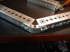
If you remember the earlier post Keeping Tabs on McGoon we laid out a home base type of form factor for the robot. This is based on sound practices in that triangles are fairly stable, and, it gives us a fair amount of room for adding things later. The other side of that coin is that the Tetrix stuff is built primarily on 45 degree angles (0, 45, 90, 135, 180, and etcetera) and fixed lengths, so we are a little limited in how we put things together. How do we make this work, we improvise! Because our robot won’t be carrying huge loads we can compromise a bit on the structure, and actually make the robot a bit more furniture and ankle friendly. We will use some flat plates in the kit that we will form into arcs for our corners.
Now, it may not be very evident, but here is the the first mistake I made while building the base. Do you see it? Anyone? I attached the plate too far up on the piece so it would not have room to make the bend it needs for the corner. This is much more what we need for the corners… You can see that having the flat plate so far up would never have worked without cutting the pieces. I probably should have mentioned this before, but I am trying to leave the pieces whole for this go-round because it is a “temporary” platform.
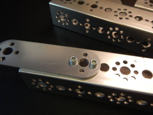
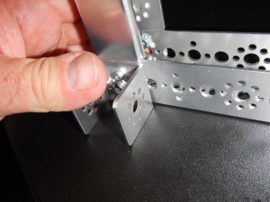
So using that technique I built the angled joints and then I used the same plates to join the top and bottom for the 90 degree angles at the front. Next comes the wheels. Tetrix uses brass bushings to support the axles and it is always a good idea to have at least TWO bushings per axle. So, we use a small piece bolted to the bottom of the frame for both front wheels.
This gives us two holes to insert bushings into for axle support. Note that I used all four screws on this mount. I did that to maximize the strength of the piece and keep it as rigid as possible. Once the bushings are inserted everything should be good and stable.
Makin’ It Move
Now let’s talk about drive motors and the drive train… There are three main methods for driving wheel in the Tetrix set; 1) Direct connection to the motor output shaft, 2) Connection through gears, and 3) connection through a drive chain like the one on a bicycle. I have chosen to use the chain for this project because it is lighter than the gears (Textrix gears are really beefy) and I don’t like direct drive as the bearings on the motors really aren’t good for supporting the whole robot and it may make the motors fail sooner.
Next Time
I think that is about it for today. Next time we will look at mounting the front motors and setting up the chain and sprockets to drive them. Until then, please keep those cards and letters coming (well, you could be the first
P.S.
I have been reading a lot about AI lately, both fiction and non-fiction, and I will be writing up some of my thoughts about that reading soon as well.
AAAAHHHHHRRRRGGGG!!!!!
by russelblee on Jul.05, 2015, under Project Goon
Phew! Glad I got that out.
Well, I was about to wire up the robot and the screens on both NXT “brain” bricks died. I assumed that it was due to the firmware update, but it appears that was a coincidence. Evidently NXTs are known to have this screen issue. I am now reaching out to Lego to see what it will take to get them repaired, but until I do I am a little stalled on the robot. Hopefully I will know more by Tuesday and I can start posting some of the backlog I have waiting. Until then, please keep checking back. I have not forgotten you, I promise.
What’s up, No Posts???
by russelblee on Jun.21, 2015, under Project Goon
Well, have ya been wondering where I have been? Busy. That is really all I have in the way of an excuse. With the advent of summer comes yard work and now that the monsoons seem to be over here in Colorado it seems everything is overgrown and in need of attention. No, we really didn’t have monsoons, but we did have an amazingly wet spring including over 20 days of rain in less than a month, which really is unprecedented.
Progress
I have actually done quite a bit on McGoon I just haven’t had the quality time to sit down and write. I can build a robot 10 minutes here and 10 minutes there, but I cannot write that way. So sad
The mechanics of the chassis are assembled. I made some… shall we call them booboos… along the way. Don’t worry though, as promised I will document the mistakes along with the good stuff. Mistakes are always a part of learning so never worry about making mistakes (unless you keep making the same ones over and over again, then maybe we should talk…). I have all the electronics mounted including some we will not be ready for until the next phase of the project. I do not have any of the wiring done though.
Next Up
Next up will be a walk-through of the build, including lots of pictures. I will discuss the decisions (and mistakes) that I made along the way, my reasoning as to why I chose to go a certain way, and some other options that are also available.
So until then… which will hopefully be later this week… take care, tip your wait-staff, and remember that bartenders use your stories when they do their stand-up comedy routines so be careful what you tell them.
See Ya!
Keeping Tabs on McGoon
by russelblee on May.31, 2015, under Project Goon
Time To Build
Last time I said we would start talking about, and maybe building, hardware. Being a man of my word let’s get down to it… Oh, before I forget, I got hold of a copy of Heiserman’s book (See the first post) and am in process of re-reading it. I am finding that Peavy’s articles are a bit “lighter” than I desired so I went back to the start. I will have updates from my reading in the near future, but for now Back to the Hardware!
WooHoo! I love building things. Software is awesome but it also my full time job so there is little diversion and relaxation in the software. Building though is very therapeutic for me.
I said in the first post that I received a great set of Lego/Tetrix building stuff, so the build will be based on those. First requirement down… Oh, did I forget to talk about requirements… Naughty Russ.
Requirements
Requirements help us know what we want to do so we can figure out how to do it correctly. The more time we spend doing requirements the better defined our project is, and the better its chances for success. That said, this project is going to take an iterative approach to requirements. We will define the basic ones, get started, and then re-visit requirements, design, and build as needed. This is similar to the Agile process used for software development and it allows us to evaluate the success of the current set of requirements and make course adjustments without going back long distances. So, what are the requirements we know right now:
- Use existing hardware components
- Three wheeled – Triangles are very stable (think tripods) and have a pretty tight turning radius
- Front two wheels are driven, back is an idler
- Must have a sensor to measure the magnitude of movement
- Built with room for adding sensors and other hardware as the project evolves
So, that is a REALLY simple list of requirements. Obviously if I were doing this as a real engineering project the details in the requirements would be much, much greater. Weight carrying capability, battery size and/or life, battery type, terrain capabilities, and the like are but a few of the things we would cover. But, because this is a hobby/experiment project we won’t go quite that deep just yet.
Back to the Build
Okey Doke, Faux Pas recovered from, back to our hardware… They say a picture is worth a thousand words, and I am a really bad typist…
Please excuse the rough sketch, but at this point I didn’t think it needed extreme detail. I assume the driven wheels are fairly obvious (Please leave me a comment if you disagree and I will make sure to cover all the details). Really, I think the piece that probably deserves the most attention is the Sensor/Idler wheel combination. The purpose of the sensor on the idler wheel is to be able to give magnitude to the success of our movements. What do I mean by magnitude? Well, higher values for more “Successful” activities and lower values for less “Successful” ones. As an example; for our robot, moving forward unencumbered is a VERY highly successful activity while going in a circle is certainly movement but it is a very low success rate because you never really get anywhere. Being stalled is really no good at all, and neither is being stuck. What is the difference between being stalled and being stuck? Awesome question.
Stuck or Stalled? Why do we care?
The motors that will be used have shaft encoders on them. If you are not familiar with a shaft encoder, its basic function is feedback to the computer about how fast and how far a motor is turning. We’ll get into the specifics of “how far” once we get further into the design, but how fast needs to be measured so that we can make sure the wheels turn at the same rate when we are going straight or we will think we are going straight while we are really slowly going in a circle. Soooo, back to being stuck versus stalled. When any vehicle is stuck its drive wheels (tracks, treads, legs, etcetera) may continue to move even though the machine isn’t. When a machine is stalled, the drive mechanism can no longer move. If we were to use the shaft encoders by themselves to judge our magnitude we would ONLY know when we were stalled, not when we were stuck. Imagine the robot going merrily along and Aunt Maud walks out in front of it. The machine hits Aunt Maud, because we haven’t installed proximity sensors yet, which is bad enough, but because the motors are strong with the Force (Shameless Star Wars reference 
The Idler and the Sensor
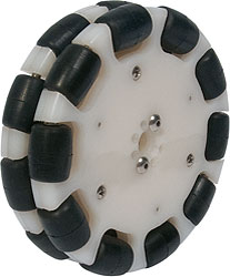
 So the wheels (I think I am going to use two connected together) that will be used for the idler will be universal wheels (also known as Omni-Wheels). These wheels have the unique ability to go in all directions. This is accomplished with little wheels within the big wheel. What this does for us is it allows us to mount the wheel facing forward without any pivot, but allows the robot to move in all directions freely. If we monitor the forward/backward rotation of the wheel we will get a “magnitude” of how well we are achieving our goal. If you want to review the goals they are here. When the robot moves forward or backward the wheels will rotate forward or backward at a proportionate rate. When the robot is turning, the wheels will rotate at a slower rate. While going in a circle, stuck, or stalled, the wheels will not rotate at all. (I will post videos of these movements once the robot is built) So how do we measure this movement? Because of how the Tetrix wheel is made we can use a light sensor. This type of sensor measures variable values of light and dark and is typically used for line-following robots that follow a dark line on a light background (or vice-versa). If we mount it right above the wheel we can monitor the dark/light transitions of the wheel as it rotates, and Ta-Da! we have a way to monitor the magnitude of our movement.
I did consider using a pivot mounted idler and measure the rotation of the wheel (With pointing forward being zero degrees) along with the rotation, but I think this option will be simpler to implement. The one concern I have is running the universal wheels on varying surfaces and how that will work. This is one of those “Try it and see how it does” things, so that is exactly what I am going to do.
Well, I don’t know about you, but I am all “Worded” out at the moment. The next post will be exclusively about assembling the robot, well it may take more than one, so be sure to check back soon. For now, Have a great day!!
Project Goon The Beginning
by russelblee on May.17, 2015, under Project Goon
Ancient History
Once upon a time when I was a young man (16) I built my first robot. I was already building computers from scratch, so it wasn’t much of a stretch. Now this robot was not particularly… ummm… shall we say functionally robust. What it really was, was a radio control tank taken apart and re-tasked into a robot. Sadly I have no pictures of my first creature, uh, I mean creation 
What’s in a Name – Project Goon… HUH?!?!
Wondering where the project name came from? Well, it is based on a couple of robot sentries from the Clive Cussler novel Dragon. Their names, given to them by the character Al Giordino, were McGoon and McGerk and their job was to keep an eye on the book’s heros and keep them from causing their owners trouble. The names stuck with me, being the nerd I am, and so I have used them in different projects over the years. I was a coach for a USFIRST FTC robotics competition teams for three years and the last year our team was named Project GERK (Generalized Entity of the Robotic Kind), so I figured it was time for a project Goon. I am still working on a clever acronym expansion, so if you have ideas drop me a comment.
How’d I Get Here?
I recently came into possession of a fairly significant set of Lego NXT and Tetrix Robotics parts which has opened up a huge opportunity for me to experiment without having to constantly buy new parts. All of my other recent projects have involved robot kits, that once they were built and I finished what I was trying, they weren’t very useful for other things. If you aren’t aware of this combination of parts, it has extreme flexibility, lots of good sensors, motors, servos, etcetera, and very solid aluminum structural components paired with Lego ease of use. All I need to add is software, well a programming environment so I can write software, and then WooHoo!! I can start experimenting my brains out.
Where Are We Headed?
So what is project Goon? Many years ago I read about, and drooled over but could never afford to build, a learning robot. The book was How to Build Your Own Self-Programming Robot, by David L. Heiserman. Since this was all the way back in 1979, I had long forgotten about it, but then while perusing the February, 2015 issue of Servo Magazine I ran into it again in an article by Camp L. Peavy, Jr., Rodney Junior: Smarter than the Average Robot. The second installment is in the May, 2015 issue. Camp’s articles renewed an old interest in me that I had wandered away from, learning robots. I have built many robots over the years; radio control, autonomous, self-navigating, but never learning. In case you haven’t figured it out yet… That’s what I am going to do in Project Goon.
The first phase in the project will be in keeping with Heiserman’s original work. By that I am referring to the three initial levels of machine learning: Alpha (α), Beta (β), and Gamma (γ) (This will be the discussion topic for the next post). Once those three basic levels have been developed and tested, I will begin adding sensors for various purposes. Hopefully somewhere around the third or fourth phase I am hoping to maybe add machine vision and object recognition, trying to keep the machine learning active throughout the project.
That’s it for today, but I will post more soon. Stop back or follow me to keep up to date.


